A clock circuit is a circuit that can produce clock signals. These signals are digital square waveforms, which alternate between on and off.
This is important because many different types of chips need clock signals in order to operate. Many chips such as counter chips, digital potentiometers, and many other types of ICs need clock signals in order to operate. The clock provides a way that a master and slave device can act in synchrony with each other. Either on the falling or rising edge of a clock signal, the 2 devices will work in synchrony so that they can produce a desired outcome.
With a 555 timer, we can produce clock signals of varying frequencies based on the values of the external resistors and capacitor that we choose.
We can produce clock signals of any frequency needed. A 1Hz clock signal will cycle once every second. A 2Hz clock signal will cycle every 0.5 seconds. A 100KHz signal will cycle every 0.00001 seconds or every 10 microseconds. The time period, T= 1/f, where f is the frequency of the signal.
For the 555 timer to work, it must be operated in astable mode. Astable mode is a mode in which there is no one stable state. The circuit switches constantly from low to high, which is representative of a digital square waveform that goes constantly high to low, high to low, high to low, over and over again. So the astable mode switches constantly between HIGH and LOW states. This is in contrast to the other 2 modes, monostable mode and bistable mode. Monostable mode has one state, either HIGH or LOW. Bistable mode has 2 stable states that it can be in. Like astable mode, bistable mode has 2 states but they’re stable; in astable mode, they constantly fluctuate back and forth between the 2 states.
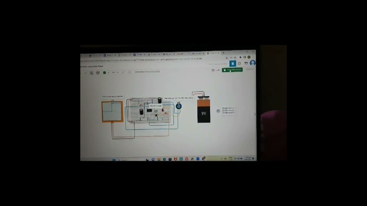
A 555 timer is a very versatile. In this circuit, we will build a clock of about 60Hz. This cycles 60 times every second.


Comments