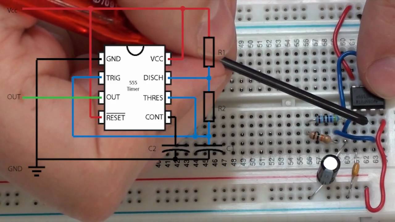
This is an experiment to set up a low frequency clock signal that we can use to drive our logic gate circuits. The clock will have a frequency of 1Hz, which will allow us to see the changes to our circuit as the clock cycles. This is one of the experiments related to EE223, an introductory module to digital and analogue electronics at Dublin City University. The associated details are at: http://www.eeng.dcu.ie/~molloyd/EE223/
Experiments 4.1 : Applications – The 555 Timer Sequence
 テクノロジー
This is an experiment to set up a low frequency clock signal that we can use to drive our logic gate circuits. The clock will have a frequency of 1Hz, which will allow us to see the changes to our circuit as the clock cycles. This is one of the experiments related to EE223, an introductory module to digital and analogue electronics at Dublin City University. The associated details are at: http://www.eeng.dcu.ie/~molloyd/EE223/


Comments